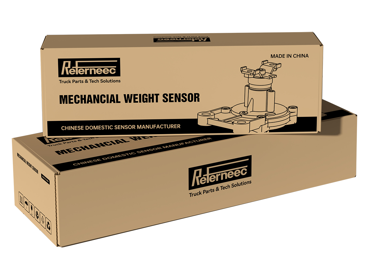
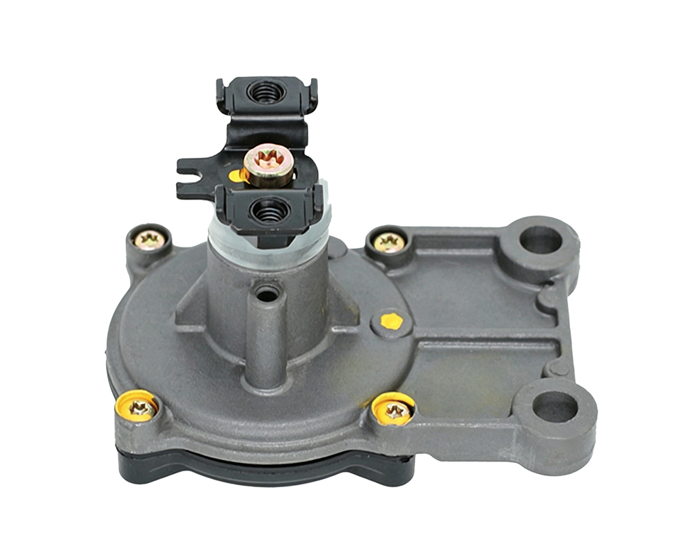
Mechanical weight sensor
Professional sensor technology provider for commercial vehicles and lot applications.
Mechanical weight sensor
Professional sensor technology provider for commercial vehicles and iot applications.

Mechanical Weight sensor
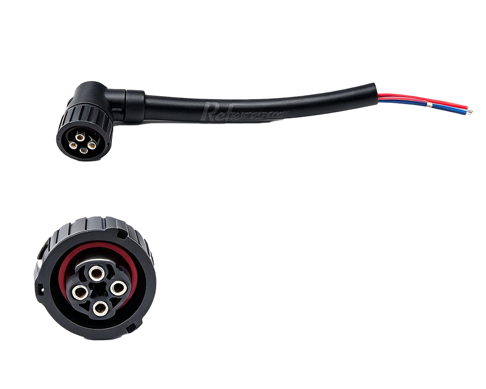
Connector
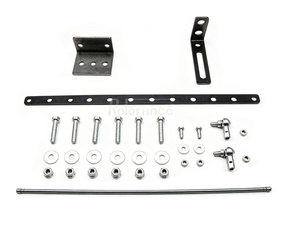
Repair kits
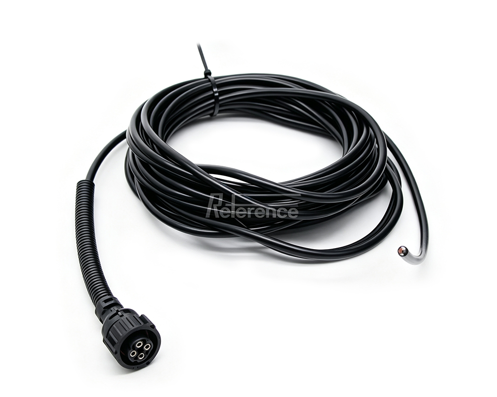
Connector
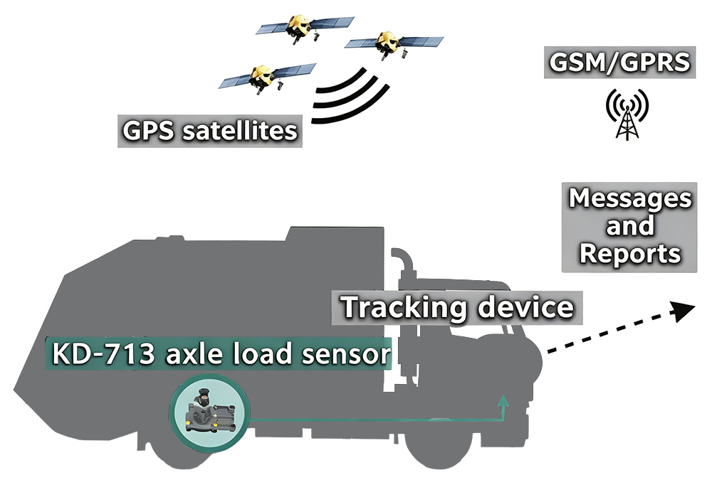
1.1 Production Introduction
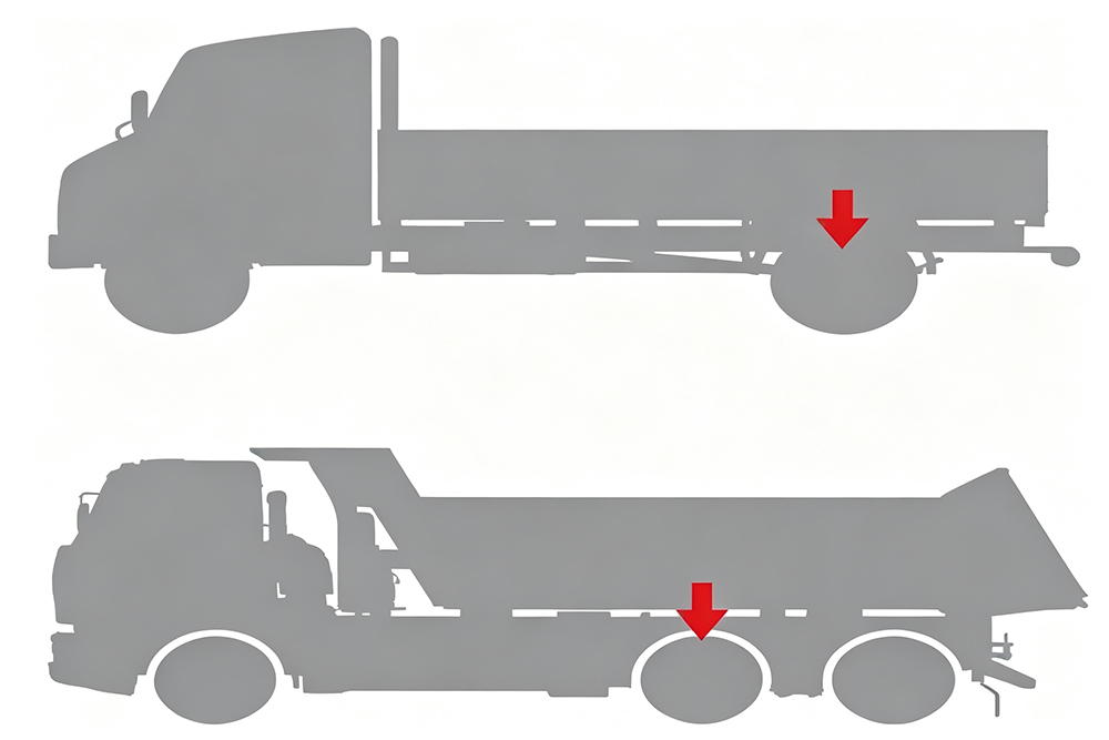
KD-713 Axle load sensor is designed for axle load and cargo weight monitoring through vehicle tracking systems. Axle load sensor can be connected to analog input of tracking device .
With the help of axle load sensor, vehicle tracking system receive necessary information about location and time of loading and unloading the vehicle.
1.2 Design Principle
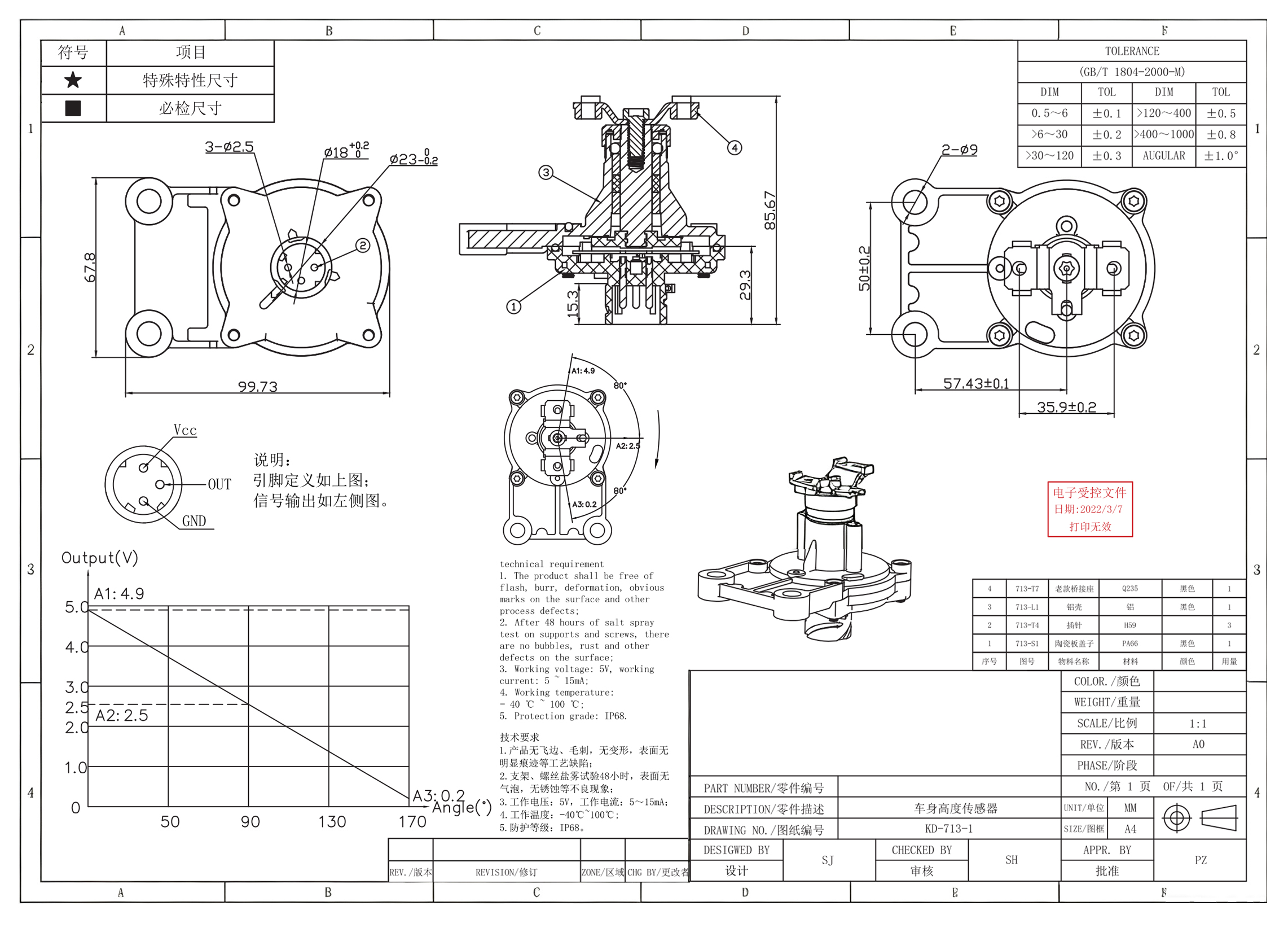
KD-713 is an angle sensor based on a carbon film brush, The sensor will output different resistance values at different angles. The outside of the product can be measured by resistor voltage division method.The product can only output analog signals .
1.3 Working Principle
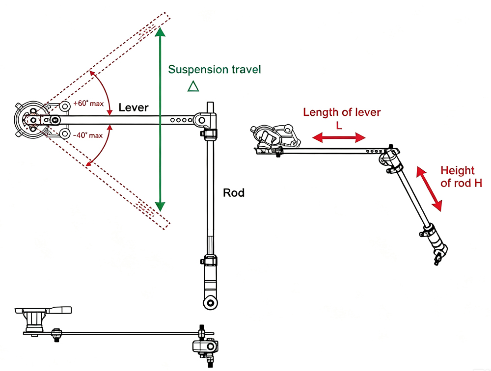
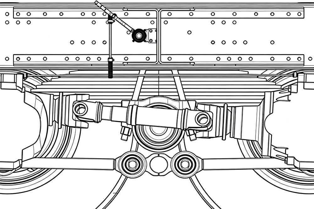
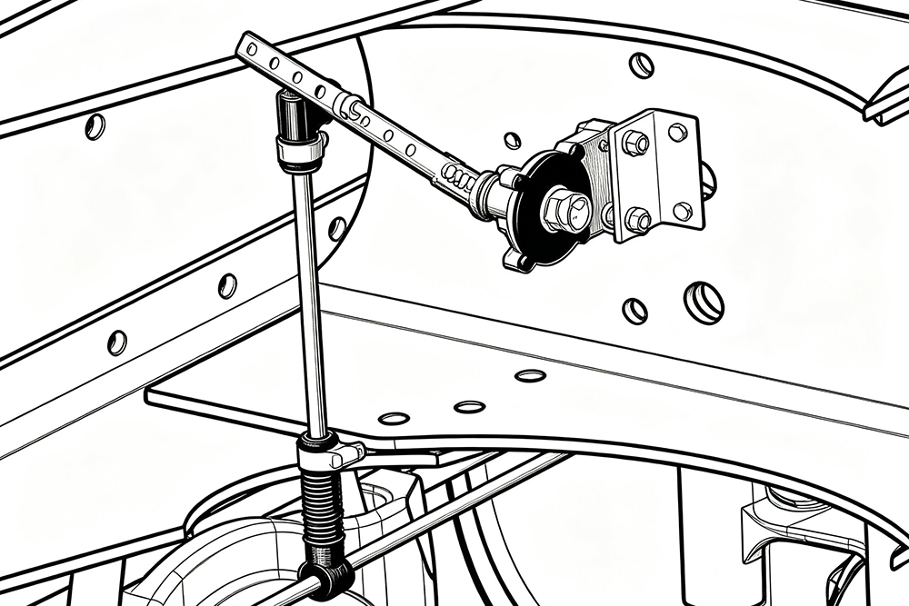
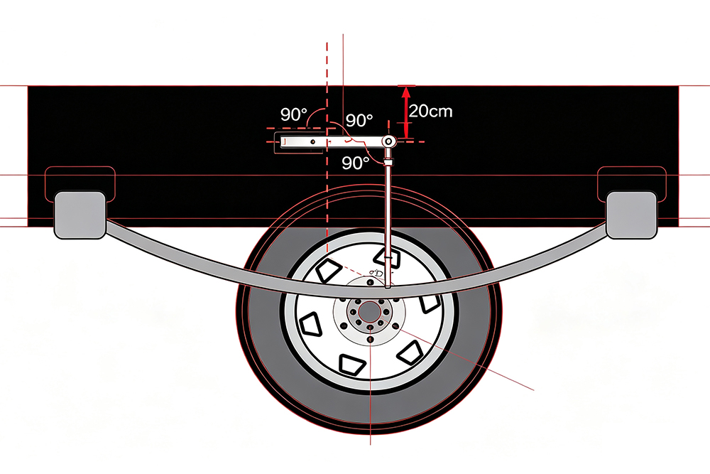
KD-713 is designed for vechicles with leaf springs suspension. We use the lever principle to install the sensor on the truck frame, usd our customized repair kits to fix the device on axle .When the loading of vechile changes , the distance between frame and axle will change as well, KD-713 will output different datas based on the changes.
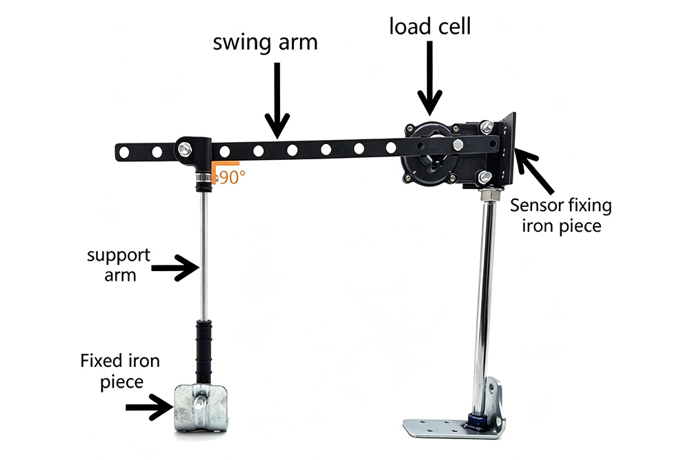
2.1 Structure Drawing
2.2 Installation Instruction
|
1. Use'plate1 ' to install the Kd-713 on the vehicle frame.
|
|---|
|
2.Use ' plate 2 ' to fit the sensor assembly to the rear or front axle
|
2.3.1 Installation Diagram
2.3.2 Repair Kit Usage Diagram
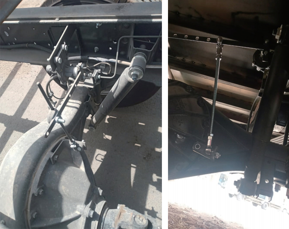
2.3.3 KD-713 Sensor Customer Installation case
Note: This case is from Saudi Arabia
3.1 Basic Parameters
|
Operating Voltage:
|
V-24V
|
|---|---|
|
Operating temperature:
|
-40~105
|
|
Output signal:
|
0- (5V-24V)
|
|
Product weight:
|
290g
|
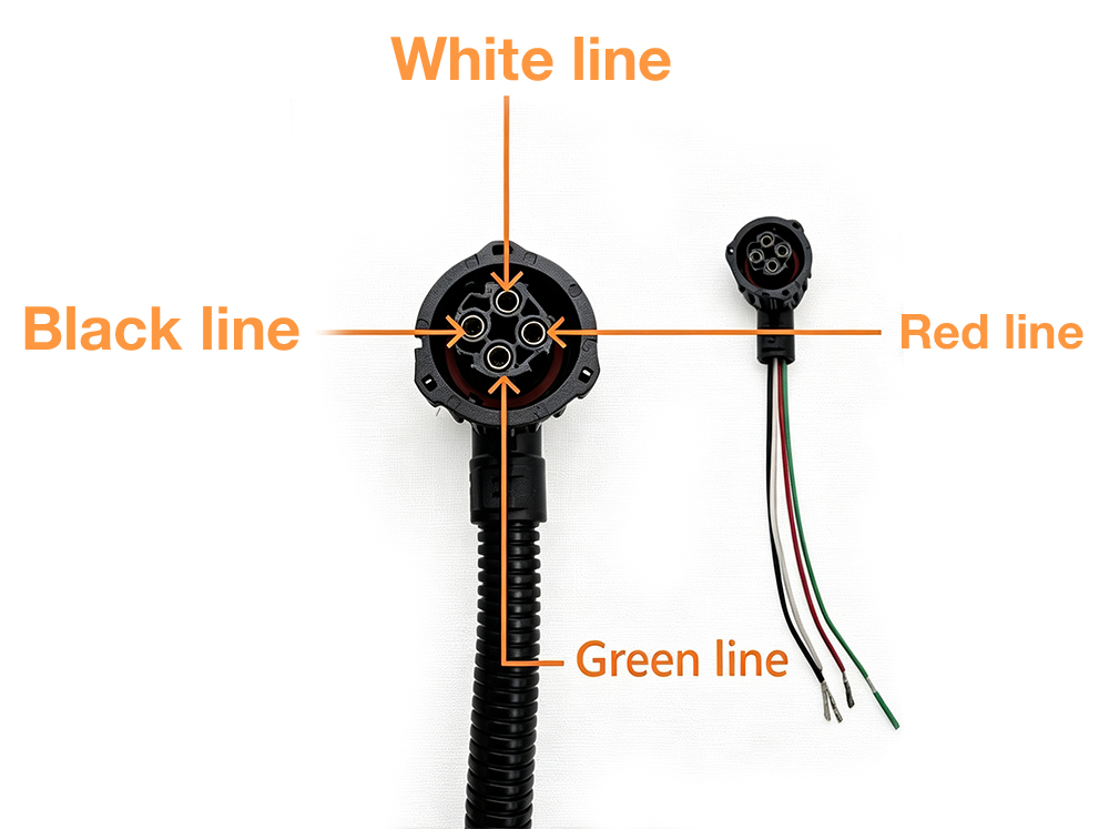
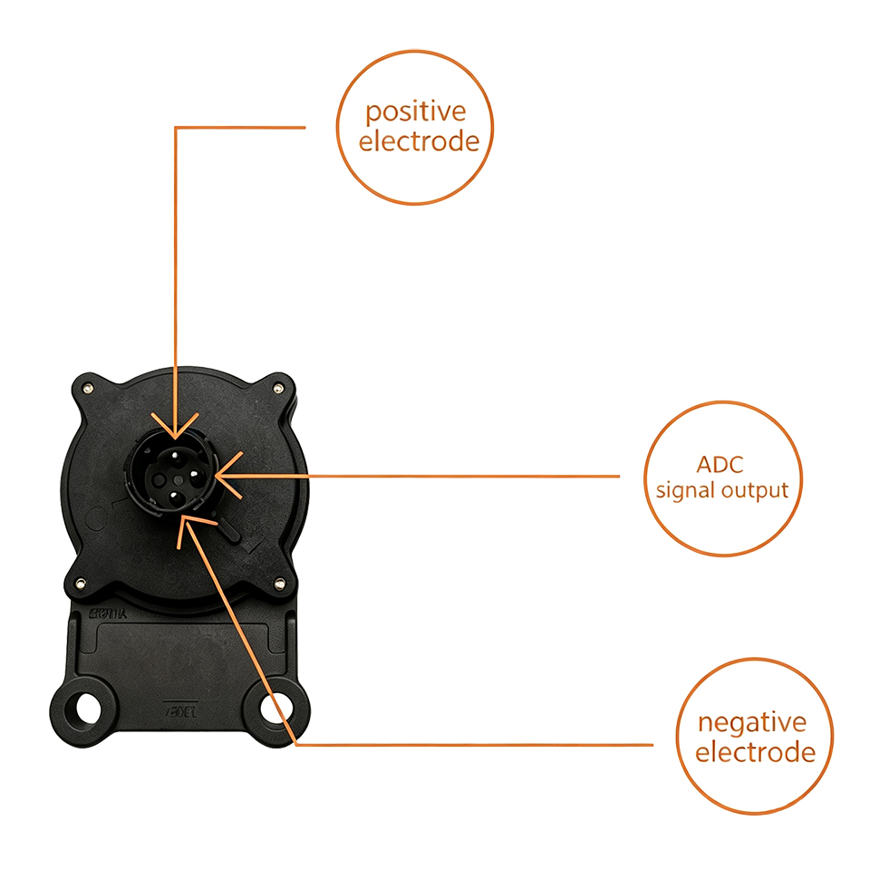
3.2 Wire Configuration Diagram
|
4 Pin Plug
|
Load Sensor
|
|
|---|---|---|
|
1-Red line
|
Product positive electrode
|
GND
|
|
2-black line
|
Product negative pole
|
V+
|
|
4-Green line
|
ADC signal output
|
ADC
|
|
3-White line
|
|
|
4-pin plug pin description diagram

Load sensor 3 pin description
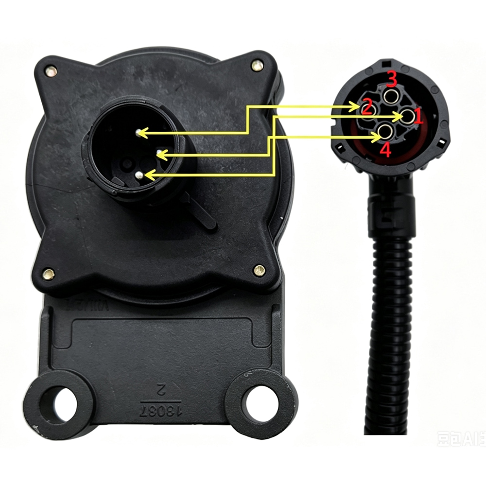
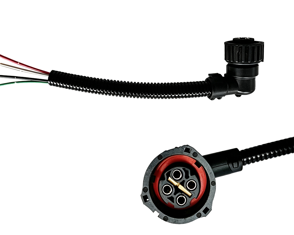
Load sensor and 4-pin plug connection diagram
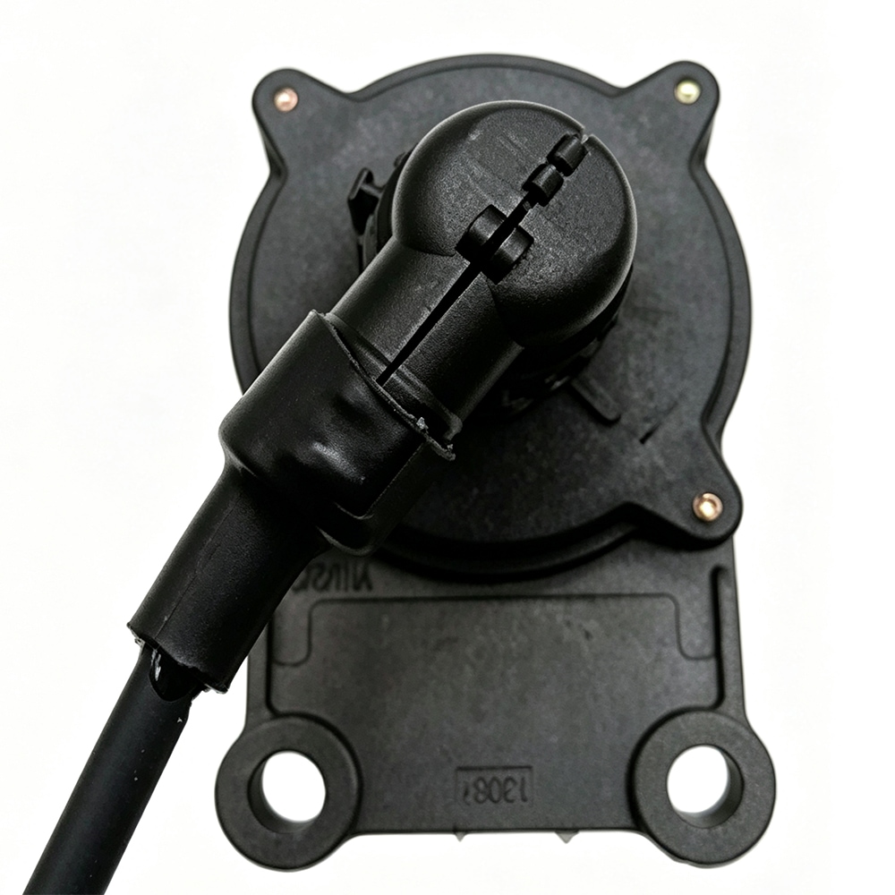
Schematic diagram of the use of load sensor and 4-pin plug
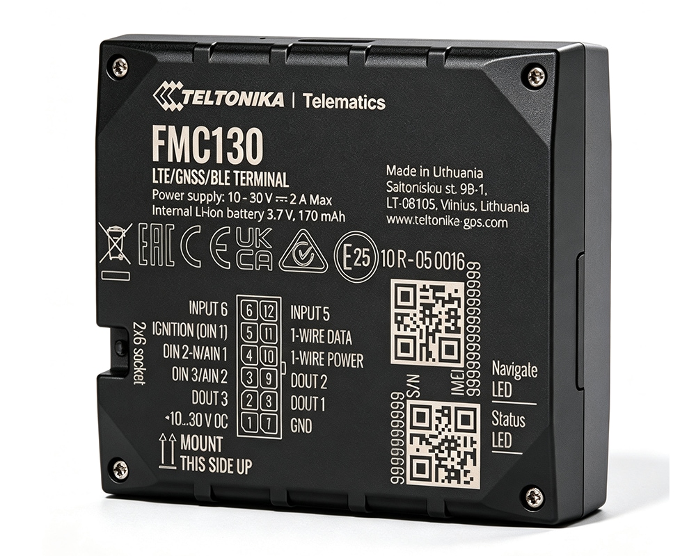
3.2.1 Wire configuration Diagram Installation case
(The two pictures represent the product and plug respectively)
The above is a demonstration for Saudi customers to use the load sensor with TELTONIKA GPS FMC130. Just connect the positive and negative poles of our product to FMC130, and then connect our ADC (green wire) to No. 11(1 wire data) of FMC130.
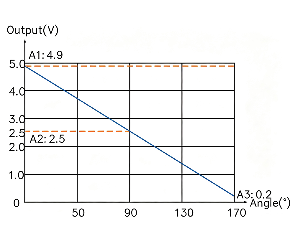
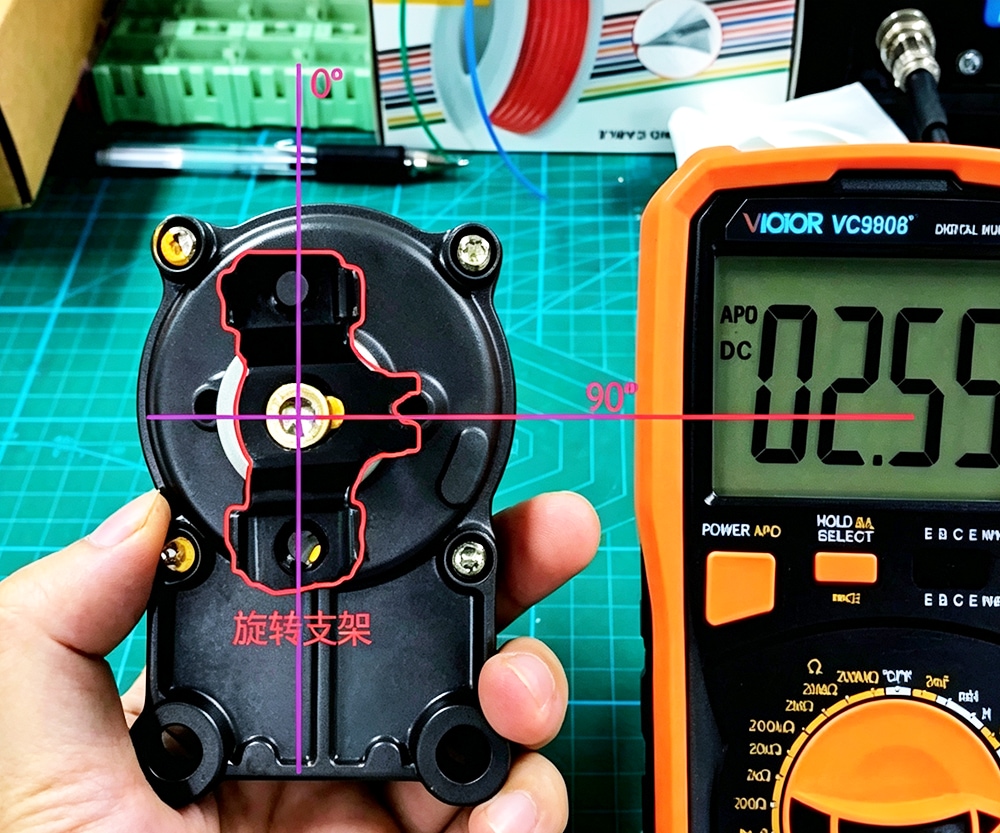
3.3 Sensor test report data sheet (angle & output voltage)
|
Angle(°)
|
Voltage(V)
|
|---|---|
|
10
|
4.896
|
|
20
|
4.644
|
|
30
|
4.341
|
|
40
|
4.05
|
|
50
|
3.748
|
|
60
|
3.432
|
|
70
|
3.129
|
|
80
|
2.814
|
|
90
|
2.511
|
|
100
|
2.17
|
|
110
|
1.868
|
|
120
|
1.552
|
|
130
|
1.237
|
|
140
|
0.934
|
|
150
|
0.644
|
|
160
|
0.314
|
When we change the angle of the load cell the voltage output by the product will change accordingly. The voltage changes linearly with the change of angle.
When the product is as shown in the picture above, it represents 90 degrees
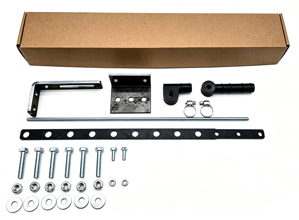
4.1 Introduction of Repair kits
|
No.
|
Name
|
Photo
|
Remarks
|
|---|---|---|---|
|
1
|
Repair Kit
|
|
|
|
2
|
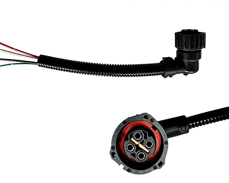
Extension Cable
|
|
4 Holes+20CM
|
|
3
|
Extension Cable
|
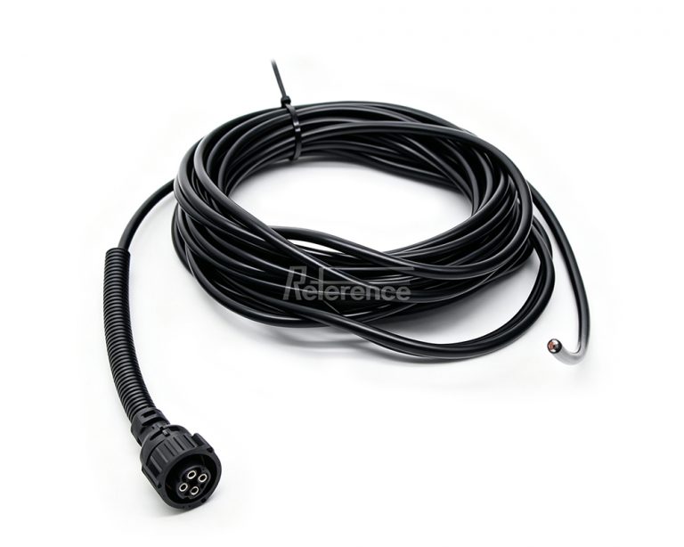
|
4 Holes+10M
|
Remarks: These accessories are freely chosen by the customer and can be purchased together with the load cell,or only the load cell can be purchased